Video security camera interface
BNC
BNC connector is a connector used for coaxial cable, used for radio frequency signal transmission. Mainly used for coaxial analog cameras, SDI digital cameras, DVR video input/video output and other interfaces. According to the appearance, it is generally divided into two types: male and female.
BNC, the full name is Bayonet Nut Connector (Bayonet Nut Connector, this name vividly describes the shape of this connector), also known as British Naval Connector (British Naval Connector, may be the earliest use of this connector in the British Navy) or Bayonet Neill Concelman (Neill Concelman bayonet, named after its locking method and its inventor, Paul Neill of Bell Labs and Carl Concelman, an engineer from Amphenol.)
BNC connectors are available in 50 ohm and 75 ohm versions. When the 50 ohm connector is connected with other impedance cables, the possibility of transmission errors is less. Connectors of different versions are compatible with each other, but if the cable impedance is different, the signal may reflect. Usually BNC connectors can be used at 4GHz or 2GHz.
RJ45(POE)
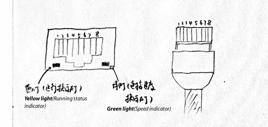
RJ45 network cable interface, a total of 8 wires and 4 pairs. To be accurate, it should be 8P8C, which is often mistakenly called RJ45, which is a commonly used connector plug for Ethernet using twisted-pair connection.
8P8C is 8 position 8contact, which means 8 positions (Position, groove), 8 contacts (Contact, metal contact).
In T568A, 8 wires are defined as: white green (Tx+), green (Tx-); white orange (Rx+), blue (BI+); white blue (BI-), orange (Rx-); white brown ( BI+), brown (BI-).
In T568B, 8 wires are defined as: white orange, orange; white green, blue; white blue, green; white brown, brown.
In Fast Ethernet, only four wires 1, 2, 3, and 6 are used. In Gigabit Ethernet and POE power supply, all four pairs of wires are used.
HDMI/VGA
The HDMI/VGA interface is commonly used in DVR/NVR, and is used to connect to the monitor to output the displayed image. It is relatively rare on general cameras, but there are actually some.
For example, the SDI camera itself outputs digital signals, and it is natural to switch to HDMI interface output. For example, in a network camera, before encoding a digital signal into a network signal, the general sensor supports the direct output of the lvds signal, and it is logical to directly output the lvds signal through the HDMI interface. Only the camera directly outputs the image through HDMI, HDMI transmission distance is limited, except for video conferencing, it is rarely used for other purposes.
Audio in/out
The camera can have built-in pickups and speakers, of course, can also be external. For external pickups and speakers, the Audio in/out audio interface is generally required.
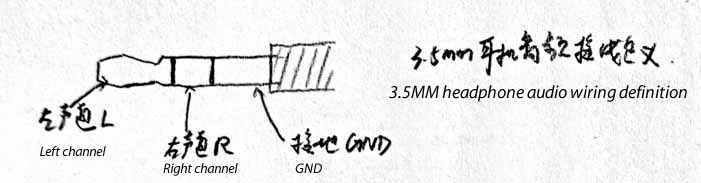
If you are using a 3.5mm audio interface (also called 1/8’ connector), you may need to distinguish between left and right channels. If dual channels are not supported, generally choose to connect the front left channel.
Some camera audio interfaces use RCA interfaces, commonly known as lotus heads.
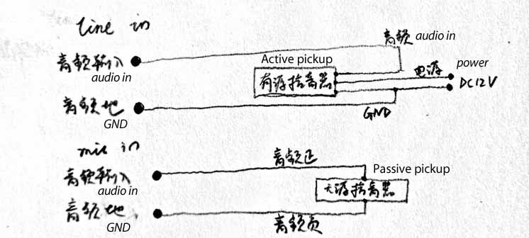
The audio input of the camera generally has Line in and Mic in to choose from. Line in and linear input need to be connected to an active pickup, that is, the pickup needs additional power supply. Mic in is used to connect passive pickups, and the pickups do not need a separate power supply.
Alarm in/out
The camera can be connected to an external alarm device, alarm input and output.
Human body sensing, light sensors, etc. are alarm input devices. The alarm input supported by the camera is generally a normally open/normally closed switch signal. Normally open or normally closed can be set and selected in the camera.
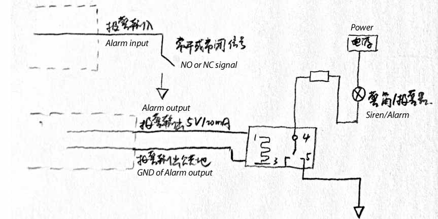
Alarm output devices are generally horns, siren, etc. The alarm output signal of the camera is generally a normally open/normally closed switch or high and low level. Normally open, normally closed, high and low level etc. can also be generally set in the camera parameters.
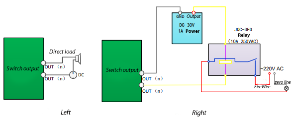
When the alarm output is a switch value, an external power supply is required when connecting the alarm. When external DC power supply (specific wiring method, as shown on the left side), the external power supply generally must be within the DC 30V voltage and 1A current limit. When the external AC power supply is connected, an external relay must be used (specific wiring method, as shown on the right side of the figure below). If the relay is not connected, the equipment will be damaged and there will be a risk of electric shock.
Special attention should be paid to the electrical performance of the alarm input/output interface supported by the camera. Exceeding the rated value may damage the equipment.
The above alarm input and output interfaces are usually designed as the appearance of wiring terminals, commonly known as phoenix terminals. The following RS232, 485 interfaces and some DC12V/AC24V power interfaces are also designed as Phoenix terminals.
RS485/232
The RS485 interface on the camera is generally used to control the pan/tilt rotation, and the RS232 interface can generally be used to connect a computer to the camera for communication, such as writing and burning firmware. It can also communicate with other devices, such as cash registers, and superimpose data.
According to the RS-485 industrial bus standard, the RS-485 industrial bus is a half-duplex communication bus with a characteristic impedance of 120Ω, and its maximum load capacity is 32 effective loads (including master control equipment and controlled settings).
RS-485 connection methods generally include daisy chain connection, simplified connection, star connection and so on. When using star connection, an RS-485 splitter is generally required.
USB
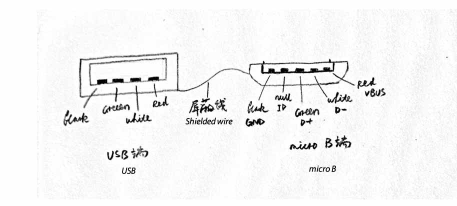
The USB interface on the camera can generally be used to connect an external U disk for storage (TF card storage is generally transferred through the USB interface expansion), and it can also be connected to an external USB interface Wi-Fi/4G module to expand Wi-Fi, 4G functions, etc. . Special ones can also be used to connect to other USB devices, such as USB card readers.
DC

Camera power supply interface. Generally DC12V or AC24V. Need to pay special attention to the size of the camera’s power interface, the most common is the interface with an outer diameter of 5.5mm and an inner diameter of 2.1mm.
RESET
Restore factory button. After the camera malfunctions or the settings are confused, the camera value can be restored to the factory default state by long pressing the reset button.
TF/SD slot
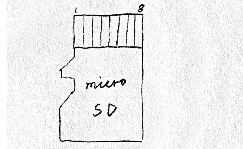
Insert TF/SD card for storage. It is usually transferred out through the USB interface extension.
Aviation head
For some vehicle-mounted cameras, DVR combines the power supply of the camera and the video interface to form a connector for power supply and convenient and stable connection.
Fiber optic connector
In order to facilitate long-distance transmission through optical fibers, some cameras have their own optical fiber interfaces, which can be inserted into optical modules and communicate directly through optical fibers.
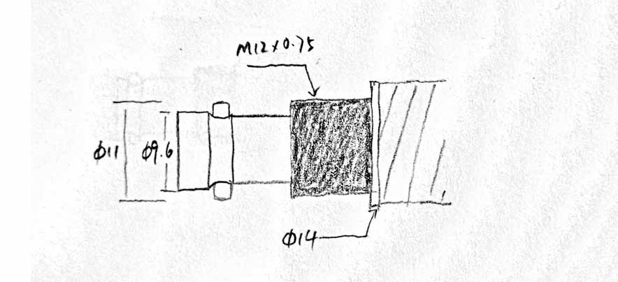
Wi-Fi, 4G antenna interface
The camera supports Wi-Fi and 4G functions, and generally requires an external antenna. The connector that connects one end of the antenna to the main board of the camera is called U.FL, also called IPX or IPEX, and the other end that connects to the antenna pole is called SMA connector, which is divided into outer screw inner hole and outer screw inner pin. The corresponding antenna pole connector is Inner screw inner needle and inner screw inner hole.
Auto iris lens
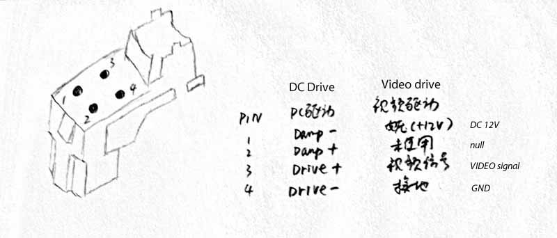
Common automatic iris lenses include DC drive, video drive, P-iris, i-CS, etc.


Leave a Reply
Want to join the discussion?Feel free to contribute!